1ko
I'm working on a tray drawer (for the curious, it's for the Tesla Model Y front center box). Using FreeCad 0.22 dev, the model will be 3D printed.
With your help I could made it how I wanted. However as I'm a beginner with FreeCad, there's a lot of ugly things. So I wanted to work on this new iteration and clean it up as much as possible, mainly to learn the software.
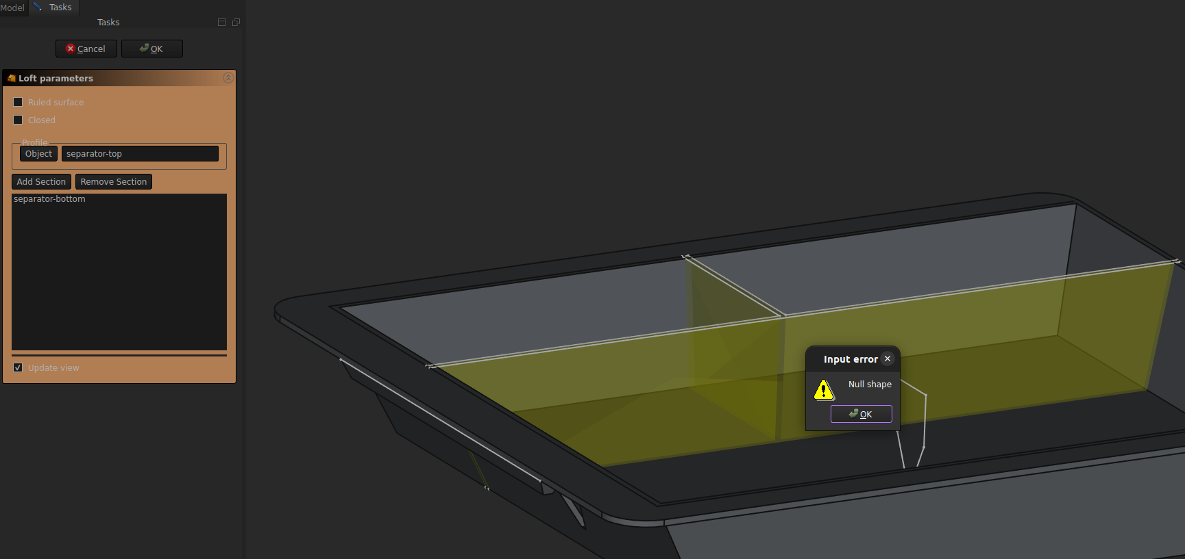
I have 1 major problem: I can't make a loft between my to sketches to create the separators. And I don't understand why.
Another point I do not fully understand is the construction lines. Should I use the External Reference or a Carbon Copy ? I don't really like the carbon copy as there's to much things displayed and sometimes I'm lost and don't see my original sketch anymore. For example, my bottom separator sketch must be linked somehow to my bottom box sketch, so if I change the position of the bottom of the box, the separator will adjust automatically.
Here's an image of how the model should look (my previous iteration) https://imgur.com/a/H8on1MZ
and here's he file I'm currently working on. license CC0 1.0 (you can do whatever you want with it) https://drive.google.com/file/d/1WSgCSVhF1Io7ynhOXDkcO1hc8piln_mg/view?usp=sharing
I'm new to freecad, so far I made it this way :
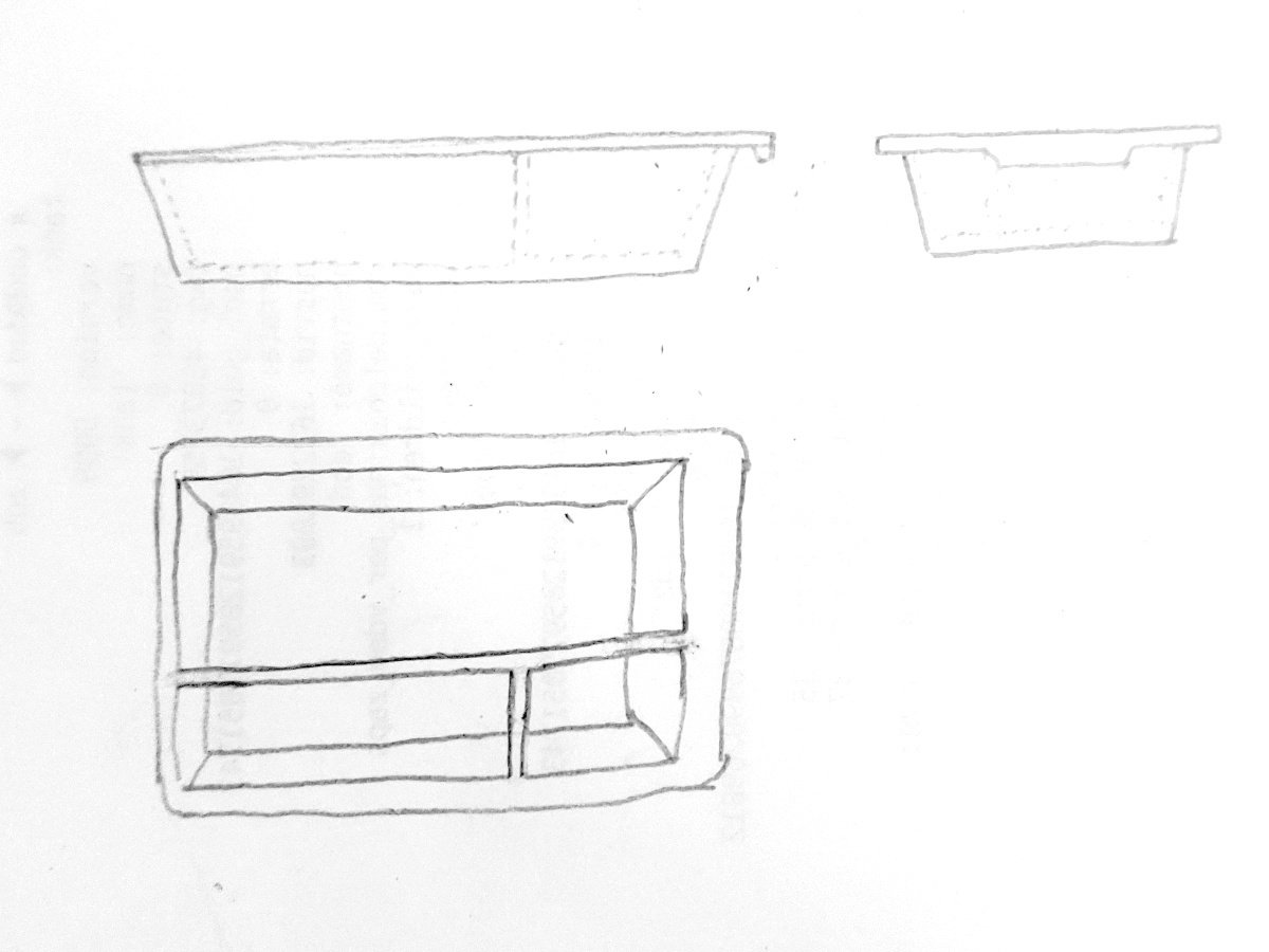
Sketch a rectangle for the top surface, pad it, add filets for the corners. Then select to bottom face, make a new sketch, another rectangle, then a datum plane 40mm below, sketch another smaller rectangle, and make a loft between the two to create the bottom of the tray.
Now for the hole I made a rectangle on the top face and made a pocket with an angle.
Downside of this, the thickness of the walls is not equal. Ideally I'd like a 1.5mm thickness everywhere. And I'm not really sure how to proceed to make the separators inside the tray.
What is the most efficient way to do it? thanks