Electronics

778 readers
13 users here now

Digital, analog, RF, microcontrollers, FPGAs.

Theory and practice. New designs, prototypes, breadboards, hacks and mods.

Show your projects, learning resources and interesting articles here.

founded 6 years ago
MODERATORS
1


TL;DW: turns out e-paper has become so good that a 1bpp image can be drawn, whithout ghosting or flashing, at 1/60 s. However, the controllers these displays ship with don't have the memory bandwidth like TFTs to enable this... until now thanks to an FPGA wizard. His monitor is a direct LCD replacement and can switch between high-quality (greyscale/high-color), fast (dithered black/color dots) and power-saving (like low-bandwidth controllers nowadays) modes automatically based on content and user preferences. Everything is open source with off-the-shelf panel and FPGA. The project is finished and is accepting preorders.
Consider watching despite this "spoiler", it's very cool.

2


I really like GaAs red, orange and yellow LEDs compared to their modern phosphor-based counterparts, as well as the yellowish GaP green, as inefficient as it is. And I also like the look of 3mm/5mm indicator lights diffused by matte plastic. However, there is a way to make them more efficient: packaging 2 chips in series into that piece of plastic! This is very common for phosphor-based LEDs in lightbulbs, where rectified mains voltage is stepped down to 100-200 V DC (or capacitively dropped and then rectified) and run through a series of LEDs: for example, 36 series chips can have total voltage drop of 108 V but to save assembly cost, only 12 5050-sized components are used with three LED chips each, wired in series. Therefore, white SMD LEDs with 2-6 series chips are widely available.

However, I'm surprised I haven't seen anyone package a good old 3mm or 5mm THT LED with multiple chips of the same color, for example 2x red or green in series for a voltage drop of 3.6 V - 4.4 V. The obvious application is an indicator light for 5V circuits where less voltage will have to be dropped on a series resistor that only wastes heat. Some mains devices also use resistive or capacitive droppers to power an indicator LED: one with 2 chips in series will require half the current for the same brightness and thus a physically 2x smaller (and thus cheaper) capacitor or resistor. Alternatively, for this application, an LED with antiparallel connections can be used to increase the flicker rate from an annoying 50-60 Hz to 100-120 Hz, plus the chips protect each other from high reverse voltage, removing the need of a diode. Such LEDs already exist (WP937EYW datasheet) but the two have different colors (all combinations of red, yellow and green are available, other manufacturers make red/white or CW/WW ones but never red/red). The alternative is to make them from SMD ones but the devices using mains indicator lamps often don't even have a circuit board and having the light-emitting chips in a package with the lens is convenient for them.

red/white 2pin antiparallel LED inside structure

3


Hi, just found my old Casio PT-87 in my parents' stuff. It's a toyish keyboard and I would like to repair it for my daughters and niece to play with it. Does anyone has its service manual or schematics?

4
5


cross-posted from: https://sh.itjust.works/post/13637559

Hello everyone, I need some advice.

I am making custom PCBs for a project of mine. It's basically for a little remotely controlled robot using little DC motors. I chose the Seeed Studio XIAO ESP32C3 as the uC since it has inbuilt wifi/bt, 3.3V regulator that I can use to power the motors (can source up to 700mA) and lipo charging management (the robots will run on battery). As you can see from here, the microcontroller is surface mounted and the pads for the battery are on the bottom layer. Same story goes for the thermal pad of the microcontroller and the thermal pad of the motor driver (datasheet). I have worked with SMD components in the past and can solder them by hand, but I have never worked with SMD components that have thermal pads on the bottom layer. My question is: how to manage (route?) them? My PCB is 2-layer and I was planning on having both layers filled with a ground plane. Do I just connect thermal pads to the ground plane and call it a day? Wouldn't that make the components hard to solder with hot air? Do I make an isolated polygon that only acts as a thermal pad?

Speaking of soldering is even hot air the way to go in this case? My PCB has components on both sides, and I was planning on ordering stencils together with the boards and using solder paste, placing the components and then using hot air to solder the components in place. I thought a hot plate would be better but I don't have access to one and I don't know how that works with components on both sides.

I attached some photos of the PCB in Kicad, and here's the git repo. If it is of any help, I'm planning of having them manifactured by JLCPCB. It is also my first time using KiCad, so go easy on me :)

Thanks!

6


The lower part of my screen is updated one frame earlier than the upper part. I was able to isolate the error to the HDMI output of my laptop. The screen or cable is not broken, as I don't get these errors with other connected devices. I am assuming it is some hardware defect. Does anyone know what it could be and how I could fix it? Here are a few pictures that show the problem: pixelfed

Solved: Ok, it seems to have been a software problem. That had to do with the sync. I have installed ubuntu on the laptop for now and everything works again. Some update seems to have shot something. I am now using a

7


What I ended up doing was making my own battery by using 2x18650 connected in series to get the 6V the camcorder needed and a buck converter and worked like charm. I didn't want to end up buying already "built" batteries from a seller in Aliexpress.

Here I wrote a little more about it with images. https://0x00.cl/blog/2023/making-my-own-battery/

8
1
submitted 3 years ago* (last edited 3 years ago) by 0x00cl@lemmy.ml to c/electronics@lemmy.ml


Hello,

I have an old sony camera that has an old Ni-Cd battery (6V 3000mAh) and of course now the charge doesn't last long. They do sell "new" batteries for it but its from Aliexpress and I don't want to rely on 1 not so reputable seller incase I need a new one. So I wanted to repair it and "upgrade" it myself, but im no electrician or anything I just like to tinker with electronics so I had a few questions.

The battery and camera only have 2 connections, positive (+) and negative (-). I saw on aliexpress that they sell a 6V 4200mAh battery pack, which is made of 5xAA (1.2V) Ni-Mh rechargable batteries. Would it be as simple as that, if I connect the positive and negative to the corresponding ones on the old camera it should work?

Is there anything else I should take into consideration?

EDIT: The camera Is a Sony CCD-TR403 EDIT2: or would it be better to build my own battery pack with 18650

9


Picked up this trackball and it works great. This GitHub also got me started with Arduino code:

https://github.com/ncmreynolds/pimoroniTrackball

10


Among other resources and tech. I used this guy's mush client a thousand years ago also. Great website.

11


So, I was buying some stuff off Mouser and off the cuff decided to buy a transformer for a DIY dual-rail power supply. I wasn't paying enough attention and accidentally bought a Wurth 760895441 resonant converter (datasheet linked). I didn't notice until I was looking at the pinout and noticed the switching frequency was 70-120KHz.

I just tinker with this stuff for fun and had never heard of resonant converters. Am I correct in my assumption that this thing cannot just be directly hooked to mains like a Radio Shack special?

12


QSPICE is a new and fast SPICE simulator written by Mike Engelhardt (author of LTspice). QSPICE was initially limited to beta testing in May, then expecting to become open beta testing in July.

Quick start gives a quick overview of the UI and other elements of the software. Below are few more videos on the features.

Importing 3rd Party Models: https://vimeo.com/828090312/aa254d2e95

Using C++ and Verilog in QSPICE: https://vimeo.com/828086789/a7ada3a5d3

13


Planning on building a flight stick for a space sim. I understand some basics and I've messed around with an Arduino and a breadboard.

In the planning stages now. Should I measure the axis and rotations on the sim stick with hall effect sensors? Is there a more precise alternative?

I would also like to control the tension on the stick with brushless dc motors like done in this project https://youtu.be/ip641WmY4pA and I think the hall effect shouldn't get interference from the motors. Hopefully.

14


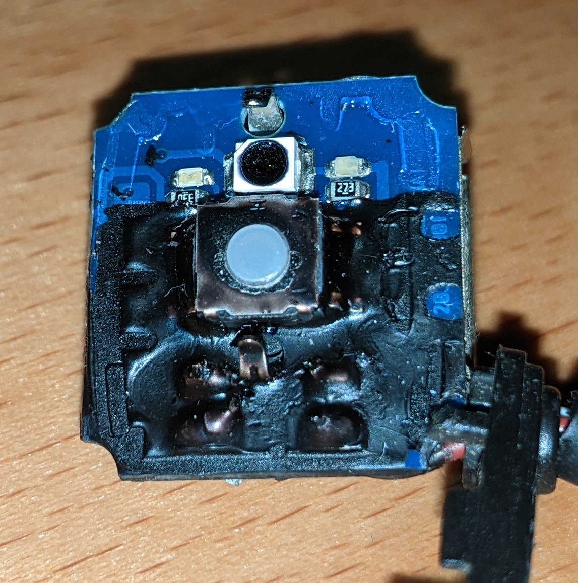
Is it supposed to be removed mechanically or chemically? Or is it supposed to stay forever? I need to redo some solder points for some components but I guess this is not possible any more, right?
15


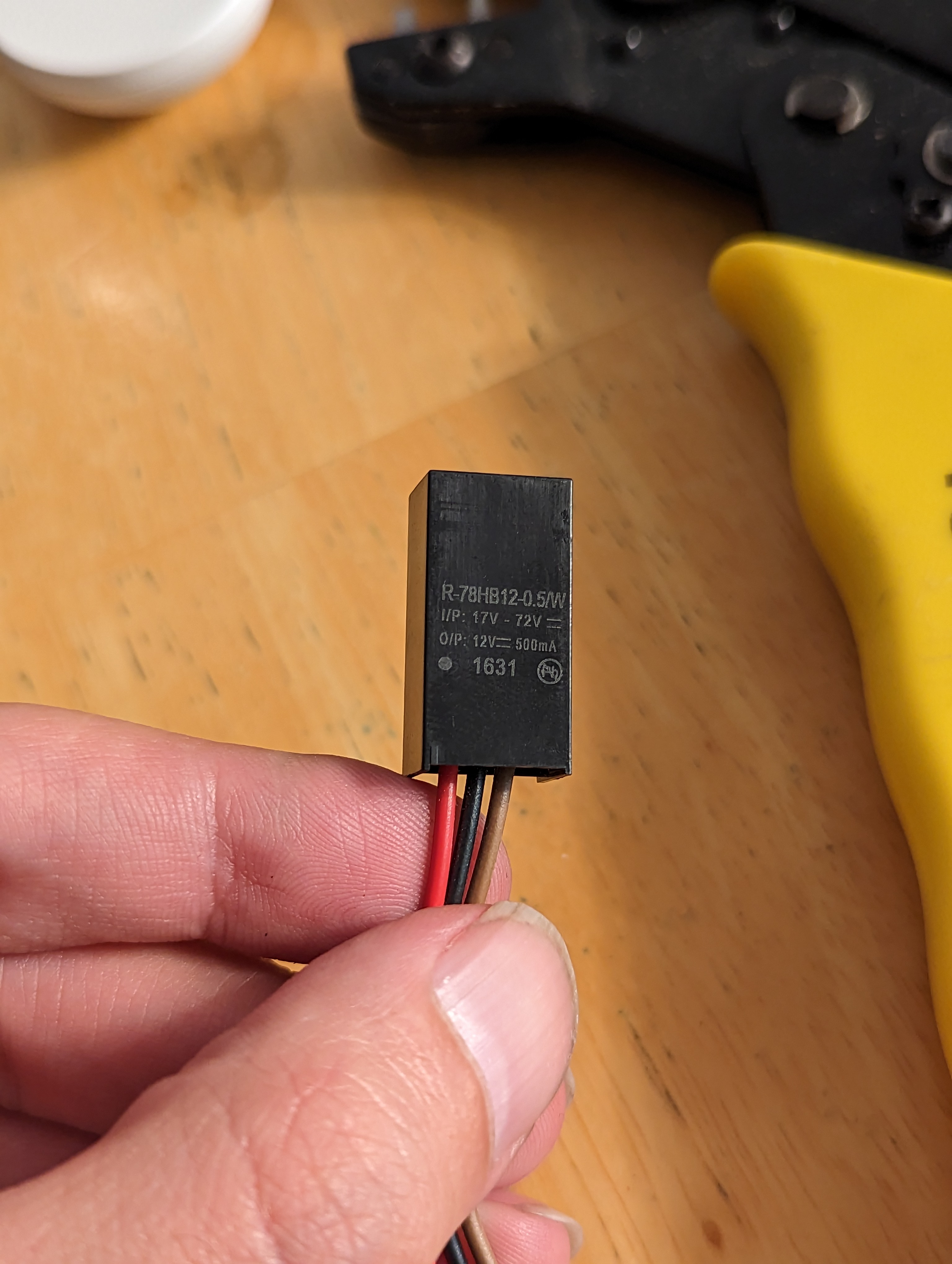
Kids, changing the polarity of components that don't seem to work in an attempt to get them to work often makes them work even less.

RIP Recom R-78HB
16


Hello!

I'm looking for a power supply that can provide 12 volts up to 5 amps that also has a USB power port I could use to power a RPI.

I've hacked an old proprietary 3d printer apart and rewired it to use Klipper running on a Raspberry Pi 3B that talks to an Arduino with a Ramps 1.4 shield to control the motors and heat element. I don't have a heated bed so would only need up to 5 amps as that's the limit of the board. Right now I have everything working plugged into two power cables, one for the RPI and the other going into the Ramps board on the Arduino. I would love to get a a device that allows me to plug a 120V AC mains power outlet into it and provide me with 12 volts 5 amps and a USB power source I can plug the pi into. Does such a device exist in a small form factor? Would love for everything to be neatly contained inside the printer.

17
18


Why is i rotated 90 degrees from the real axis? Heavy on the maths.